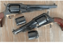
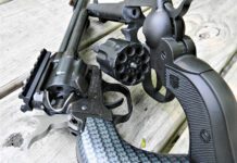
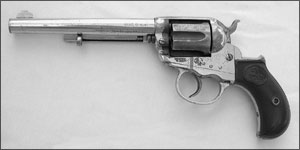
Colt’s first double-action revolver was their model of 1877, a six-shot, rod-ejector pistol capable of both double- and singe-action operation. The revolver was designed in 1876 by a well known Colt employee, William Mason. The 1877 pistols were built on a medium frame, and used a small birds-head-shaped grip. They were initially chambered only in the .38 Long Colt caliber, though the .41 Colt caliber was added later. Small numbers were also manufactured in .32 Colt caliber. “Lightning” was the nickname given to the .38-caliber versions, while .41-caliber revolvers came to be known as the “Thunderer.” These revolvers were made both with and without an ejector and in barrel lengths that ranged from 2 to 7 inches.
Author photos
300
The Model 1877 has a three-position hammer featuring a so-called “safe” position, a half-cock or loading notch, and a full-cock position. The ’77 has a frame-mounted loading gate, a feature shared with the famous Colt Single Action Army of 1873, which was also a William Mason design. Other features shared with the SAA are a two-piece removable grip frame, a removable center-mounted cylinder pin, and an ejector rod mounted on the barrel side. The similarities give the 1877 the appearance (except for the grip shape) of a Single Action Army in miniature. Appearances are where the similarities to the familiar Peacemaker end, however; the mechanical operation of the 1877 is far more complex than the SAA.
Colt made almost 167,000 Model 1877 revolvers from 1877 through 1909. While the large number of weapons is impressive, also impressive is the percentage of these revolvers that will be found to suffer from mechanical problems. Experience has shown that these handy-sized double-actions were mechanically delicate—and much less dependable than their single-action cousins. Because of that, I’ll add this note of caution: The mechanism used in these Colt revolvers is as delicate as it is intricate, and many of its critical components are prone to breakage.
Basic Repair Considerations
If you haven’t already guessed, I’ll tell you in no uncertain terms that this is not a design that I regard very highly. Due to its mechanical shortcomings, you’ll want to think long and hard before agreeing to attempt a repair on an 1877. If you decide to proceed, Ed Cox (www.coltparts.com) offers good-quality reproductions of some of the more complicated internal parts for the 1877. Because of his vast experience with this model, he’s probably the best person to contact for replacement parts. Dixie Gun Works (www.dixiegun.com) carries good-quality hand/cylinder-stop tension springs and replacement cylinder pins. They also carry a raw-cast cylinder stop that can sometimes be made to work.
300
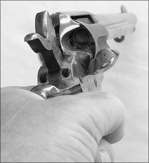
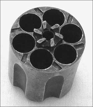
One area that is often found to be worn and is pretty easy to correct is the cylinder axis. Just like the SAA and the Model 1878 Double Action Army, the cylinder cannot have excess looseness if the revolver’s cylinder is going to time and index correctly. Many revolvers that have had hard use will show it with symptoms of incorrect cylinder indexing and poor cylinder lockup. These problems can often be traced directly to the relationship between the hand and the ratchet. Lost motion or unintended movement of the cylinder on its axis (the cylinder’s axis is the base pin) allows the cylinder’s ratchet teeth to move forward, away from the hand. That sort of play can quickly cause an 1877’s cylinder to misbehave.
When an 1877 is working well in all other areas, repairing cylinder looseness is often all that’s needed to restore correct timing. That said, removal of excess headspace and cylinder end-shake are the first repair steps to be taken, along with stabilizing the cylinder on its base pin. If your 1877’s cylinder has excessive headspace, then the ratchet teeth are also too far away from the hand; moving the cylinder rearward and holding it there will restore their correct relationship with the hand and will likely restore the timing. If we were working on an SAA, we could install a new base-pin bushing, using the added material at its front to help us get the cylinder pushed back where it belongs.
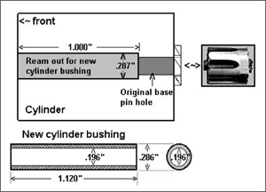
Unfortunately, Model 1877 cylinders don’t have a removable base-pin bushing, so to accomplish that sort of repair you have to do one of two things. One is to make a hardened-steel disk-shaped shim to fit over the base pin that will be located in front of the cylinder to push the cylinder backward. Or you could lathe-ream the cylinder to accept a shop-made, lathe-turned base-pin bushing similar to the bushings used on the 1878.
While you’re checking this area, test the cylinder for any wobble (side-to-side looseness). A part of the solution to timing problems is often the elimination of wobble at the cylinder axis, so this, along with the headspace repair, should to be made before moving on to the rest of the mechanism; in other words, always deal with cylinder-rotation issues first. The wobble is caused by two things: the cylinder being loose on the base pin and/or the base pin being loose in the frame.
300
Repairing a wobbling cylinder is done by reaming the base-pin holes in the frame and the hole through the base-pin bushing to a just slightly larger than standard size. By reaming the holes we are also making the worn holes round again. I use hand-chucking reamers for this job. These are available in decimal sizes in increments of 1/1000 of an inch. Begin by selecting a reamer that is just a thousandth (.001) larger than the original cylinder pin, and ream both cylinder-pin holes through the frame. Now measure the holes to see if the reaming operation has made them round. If not, select a reamer .001 inch larger than the first, and continue to increase the size in .001-inch increments until the frame holes are again perfectly round. This may involve reaming to .003 inch larger than the standard cylinder-pin hole diameter.
The cylinder-pin bushing (if you have a custom-made one) and the base-pin hole through the cylinder have to be reamed to this new size. Finally, you will fit a new cylinder pin to the frame. You can purchase an aftermarket pin or, depending on the oversize needed, custom-make one in the lathe that’s sized to be a slip-fit in the newly oversized holes.
Takedown Instructions
As I stated earlier, this unusual revolver design has a reputation for being extremely intricate, and certain of its parts are complicated and known to be highly prone to breakage. Therefore, disassembly is recommended only for skilled professional or talented amateur gunsmiths. Also, please note that the parts drawing included here is from The Gun Digest Book of Exploded Firearms Drawings, 2nd edition, edited by Harold A. Murtz (DBI Books Inc., 1977). The drawing was altered, renumbered, and edited by the author.
Safety First. Keep your fingers away from the trigger during this entire operation. Always check first to make sure this weapon is unloaded by opening the loading gate (#13) and pulling the hammer (#29) slowly to the rear until you hear two audible clicks. This should place the hammer in the half-cocked (or loading position) where the cylinder (#8) spins freely in a clockwise direction. To make sure the chambers have no cartridges in them, rotate the
300
cylinder two full revolutions by hand while examining the cylinder chambers through the opening presented by the opened loading gate at the rear of the frame (#9).
Removing the Cylinder. The hammer should still rest in the half-cocked position and the loading gate should still be open. The Model 1877 cylinder rotates on the base pin, also known as the cylinder pin (#7). This pin has to be removed from the front of the frame before the cylinder can be taken out. Depress the cylinder-pin lock screw (#10) to actuate the cross bolt which passes through the frame to unlock the cylinder pin, then pull the cylinder pin (#7) straight out the front of the frame. The cylinder is now free to be carefully rolled sideways out the right side of the frame.
Removing the Grips and Grip Straps. Unscrew and remove the grip screw (#51) from the center of the left grip and then remove the two grips (#49). Unscrew and remove the two backstrap screws (#42) from the rear of the backstrap (#41) and the butt screw #43 from the bottom of the backstrap. The backstrap (#41) can then be lifted off the frame to the rear. Loosen the mainspring-tension screw (#47) at the front, inside-lower area of the trigger guard (#44). Remove the mainspring screw (#40) from the lower inside of the trigger guard, unhook the mainspring (#39) from the hammer stirrup (#33), and lift out the mainspring. Unscrew and remove the two trigger-guard screws (#45) and the front trigger-guard screw (#46). The trigger guard (#44) is now loose and will pull down toward the bottom.
Disassembling the Action. Pay careful attention to the relationship of the parts you are about to disassemble. Unscrew and remove the sear screw (#28) from the left side of the frame. This will free the sear (#27) and the hand/cylinder-stop tension spring (#35) and they can be removed from the frame bottom.
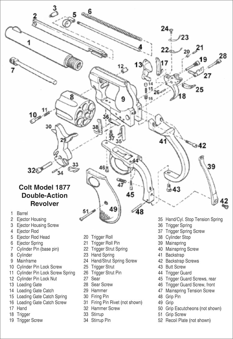
Unscrew and remove the hammer screw (#32) from the left side of the frame and disengage the trigger strut (#25) from its seat in the hammer while pulling the hammer (#29) down from the bottom of the frame. Loosen the trigger-spring screw (#37) and then remove the trigger screw (#19) from the left side of the frame. Both the trigger (#18) and the hand (#17) can be pulled out together through the bottom of the frame. The cylinder stop (#38) can now be pulled from its seat and taken out the bottom of the frame.
The trigger-strut spring (#22) and the hand spring (#23) can be removed from the trigger by removing the hand/trigger-strut spring screw (#24) from the top front of the trigger (#18).
Disassembling the Peripherals. Once the ejector-tube screw (#3) is removed from the front of the ejector tube (#2), the entire ejector-tube assembly is pulled to the side by its front until it moves slightly away from the barrel.
At this position, the assembly is pulled forward and off the barrel. The ejector rod (#4), the rod head (#5), and its spring (#6) are removed by pulling them straight back and out of the ejector tube.
Removing the Loading Gate. Under the frame in the right-side frame rail you will find the gate-catch screw (#16). Remove the screw, its plunger (#14), and spring (#15) out through the same hole. The loading gate (#13) is removed by pulling it out toward the front of the frame.
Reassemble the revolver in the reverse order of the above.


