[Updated August 29, 2018]
History of the Springfield Trap Door Rifle
Designed by Erskine S. Allin, master armorer at Springfield Armory, the trap-door rifle was originally built as a breech-loading conversion of the muzzle-loading 1861 Springfield percussion rifle. Designated the Model of 1865, 5,000 of these single-shot rifles, chambered for a .58-caliber rimfire cartridge, were manufactured at Springfield Armory.

Erskine Allin’s system involved cutting away the top section of the muzzle-loading rifle barrel at the breech. It made use of a hinged breech block that attached to the barrel top. The breechblock was locked closed into the rear of the barrel by a cam latch. In 1866, the armory converted 25,000 Model 1863 rifles to .50-caliber centerfire using the Allin system. For these rifles, they lined the .58-caliber barrel down to accept the new caliber.
This hinged-breech design was continually improved, and soon the idea of converting all the leftover musket barrels was dropped. From 1868 on, Springfield Armory made the rifles using separate receivers with new screw-in barrels in .50/70 caliber. These new rifles still made use of many parts from the old rifle musket. By 1873, the Army eventually settled on a .45-caliber rifle cartridge using 70 grains of blackpowder. The trap-door action was successfully used by the U.S. Army in regular service until it was officially replaced by the Krag bolt-action repeater in 1892. As early as the mid-1870s, it was becoming apparent (to some) that the single-shot Springfield rifle would soon be outdated by world military standards. The greatly increased firepower offered by commercially available “sporting” repeaters like the Winchester lever-action left the single-shot looking like a poor relation.
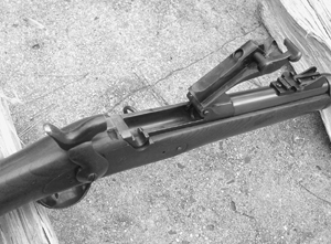
Be that as it may, the U.S. Army liked their Springfield rifle and the Armory produced over half a million of them in all, the last of these leaving Springfield Armory in 1894. Some years after its official obsolescence, the venerable trap-door Springfield was still in use by our military. In fact, many single-shot Springfield rifles and carbines were carried into the Spanish American war in 1898 by volunteers and guard units in Cuba. Pitted against the Spanish who were armed with state-of-the-art Mauser bolt-action repeaters and smokeless ammunition, the old single-shot rifles with blackpowder cartridges were hopelessly outclassed and showed they were ready to be retired.
The trap-door action was never noted for great strength, nor did it develop a reputation for reliable extraction and ejection. As ingenious as the design was, it must be remembered that it was not designed as a state-of-the-art cartridge rifle. This action system was merely an expedient which was intended to save the Army money by developing a system for converting surplus muzzle-loading rifles to shoot metallic cartridges. As history shows us, it was an expedient that worked better in theory than it did in practice.
In any case, hundreds of thousands of these trap-doors rifles, carbines, and shotguns have been sold as military surplus over the hundred years since the turn of the 19th century. As a result, the gunsmith is likely to run into many of the original variants as well as the modern-made reproductions of this grand old rifle.
Trap Door Rifle Disassembly Instructions
Note that, with some small variations, the following disassembly procedures will work for all of U.S. Springfield rifles and carbines using the trap-door system, as well as most modern reproductions of the Springfield. For part numbers, refer to the illustration on the opposite page. This drawing comes from the author’s book, Antique Firearms Assembly/Disassembly, published by Krause Publications.
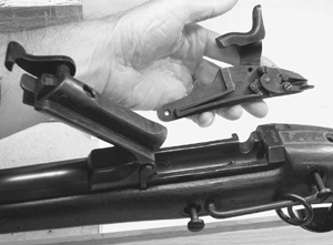
1. See exploded view, below. Always check first, of course, to be sure the weapon you are about to handle is unloaded. Grasp the rifle around the barrel and wooden forearm with your left hand and point the muzzle in a safe direction. Pull back on the hammer (#41) to place it in the loading position. (Depending on the internal lockworks, you’ll hear either one or two-audible clicks.) Then open the action by lifting up on the thumb piece (#15). This will unlatch the breechblock (#10), which you can tilt all the way up and open with your other hand.
Look down into the Springfield’s action, checking to be sure there is no cartridge in the barrel’s chamber. If you can see a cartridge in the chamber, reach in and manually remove the round by pulling the cartridge up and out the top of the action. Remove all live ammunition to a separate location—somewhere well away from the area where you are working. I prefer to store live ammo in another room altogether.
2. The next step is to remove the lock and the stock. If you’re working with a rifle, remove the ramrod (#31) first. For a rifle or carbine, leave the hammer still at the half-cock position, unscrew and remove the two side (or lock plate) screws (#20) from the left side of the stock (#24). The lock (#32) assembly can now be pulled out from the right side of the stock. Be gentle and ensure that the edges of the lock plate don’t grab any slivers of the inletted stock as you remove it.
Unscrew and remove the tang screw (#19). Depress the band springs (#30) and slide the band or bands (#25 and 26) off toward the front of the barrel. The barrel and breech assembly (#1 and #4) are now free and they can be lifted straight up and out of the stock.
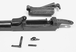
3. This next operation—disassembly of the breech and the breechbolt—frees the extractor, which is powered by a very strong coil spring. Hold your hand over the hinge area to prevent the loss of parts while performing this operation. With the breechbolt remaining in the open position, push out the hinge pin (#7) and lift the breechbolt out of its hinge in the breech (#4). The extractor (#6), ejector spring (#8), and spindle (#9) can also now be lifted out of the left-side hinge.
Make careful note of the relationship of these ejector/extractor parts for reassembly later. The point or tip of the ejector spindle has to be engaged with the detent at the rear of the extractor during reassembly. For this operation, it helps to have a long tapered punch to keep the extractor/breechblock holes aligned during the reassembly of the breechblock to the receiver.
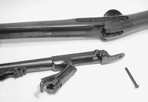
4. Disassembling the breechbolt starts with unscrewing and removing the breechblock cap screw (#16). Then remove the following parts together: the cam latch (#13), the thumb piece (#15), and the breechblock cap (#14). These parts can be lifted out to the side.
The cam-latch spring (#11) is now free and can be lifted out of the breechblock. Unscrew and remove the firing-pin screw (#17) from the bottom of the breechbolt. Now the firing pin (#12) can be removed by pulling it out through the rear. Note: Some modern copies use a two-piece firing pin with a return spring.
5. To disassembe the lock, place the hammer (#41) all the way forward for this operation. Compress the mainspring (#44) using a mainspring vise, a machinist’s clamp, or a small C-clamp far enough so you can disengage it from the mainspring swivel (#46). Tilt the mainspring out to the side, removing it from the lock plate (#43).
Reassembly tip: Since the mainspring will have to be compressed for assembly, you may want to just leave the mainspring vise or clamp in place, setting the assembly aside until you are ready to reinstall the spring.
Unscrew the sear-spring screw (#49) and lift it and the sear spring (#48) off the lock plate. Unscrew and remove the sear screw (#51). The sear (#50) is now free and can be pulled off the lock plate. Unscrew and remove the bridle screw (#53) and lift out the bridle (#52).
Unscrew and remove the tumbler screw (#42) from the center of the hammer, and insert a straight punch into the hole in the tumbler. Be sure to use a punch that is smaller than the threads in the tumbler to prevent damaging them. Tap the punch until the hammer (#41) comes loose. Now the hammer is ready to be pulled off the tumbler. Lift away the freed tumbler (#45) from the rear side of the lock plate.
Reassembly tip: As you reassemble the lock assembly into the stock, be sure to set the hammer in the loading position. Also, hold forward on the trigger as the lock plate is being inserted back into the stock to avoid any interference with the sear.
Some items of note here: Some Springfields used a two-notch tumbler (1-safety/load and 2-full cock), but the majority seem to use the familiar three-notch tumbler (1-safety, 2-load, and 3-full cock.) On H&R reproduction Springfields, the hammer screw passes all the way through the tumbler, acting as the inside pivot point for the tumbler. Original Springfields had their pivot points forged as one piece with the tumbler.
6. For disassembling the guard plate and buttplate, unscrew and remove the two guard screws (#34) from the (trigger) guard plate (#33), and carefully ease the guard plate down and out of the stock. Again, be careful with this step so that the edges of the guard plate don’t grab any slivers of the inletted stock as you remove it.
Unscrewing the two guard-bow nuts (#36) releases the guard bow (#35), which can now be pulled down and out of the guard plate. Unscrew and remove the trigger screw (#40) and the trigger (#39) will drop down and out the bottom of the guard plate. The rear sight can be removed from the barrel by simply removing the two screws that fasten the sight base to the barrel. Make note of the position of the rear sight for reassembly later.
The buttplate (#23) is easily removed by unscrewing and removing the two buttplate screws (#22). The buttplate is simply lifted off the stock to the rear. If the buttplate is equipped with a door to access a cleaning rod, remove the buttplate-door spring screw and lift off the buttplate-door spring. (Note that none of these parts are shown in the illustration.) Use a small pin punch and hammer to drift out the buttplate-door retainer pin, and lift off the retainer ring. The butt-plate door is now opened and removed by pulling it straight out the rear of the buttplate.
As always, you simply reverse the disassembly procedure above for reassembly.


